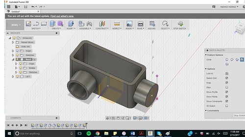
Fusion 360 Text Tutorial
Autodesk Fusion 360 is a powerful design CAD and CAM software that is free to use for hobbyists and startups with less than $100k revenue per year. This software can be downloaded from our website or directly from Autodesk. You can design your own custom 2D & 3D parts right in Fusion, or you can simply import your own part files from your favorite CAD program. The software is easy-to-use for beginners new to drafting, and Autodesk has published an ever-growing library of tutorial videos to follow along and learn.
Fusion 360 For Dummies

Fusion 360 Text Tutorials
The next step in the process is to create the toolpaths from the part file that will be followed by the CrossFire™ machine when cutting. Once your part is designed, you will use Autodesk Fusion 360's plasma CAM feature to program toolpaths based on the part geometry that you want to cut. Here you will specify cutting parameters such as cut speed, pierce delay, and lead-in geometry and Fusion will export these toolpaths as a G-code file that can be read by the machines controller software (Mach3).